
Condition monitoring for motors, pumps, compressors and fans
What actually fails on each type of rotating machine, which measurement sees it, where the sensor has to go, and why mounting method decides whether any of it works.
In short
- The machine type decides what to measure. A pump and a reciprocating compressor fail differently and a generic sensor kit suits neither well.
- Most faults are not the bearing. Misalignment, imbalance, looseness and process conditions cause more failures, and they damage bearings on the way.
- Mounting sets the usable bandwidth. A magnet base rolls off around 2 kHz, which removes the early bearing evidence entirely.
- Current signature analysis needs no machine access and is underused on awkward or hazardous installations.
- Per-machine baselines beat published limits. A tripling within the acceptable band means more than sitting near it steadily.
Why the machine type matters
Most condition monitoring advice is written as though rotating machines were interchangeable: fit an accelerometer, watch the overall level, alarm on a rise. That works often enough to be plausible and it wastes a good deal of money, because what fails on a centrifugal pump has little in common with what fails on a reciprocating compressor, and a measurement chosen without reference to the failure mode frequently cannot see the thing it was bought to detect.
This article is about that choice: what actually fails on each common machine type, which measurement sees it, and where the sensor has to go. It assumes you have decided a programme is worth running. The programme itself — strategies, the P-F interval, alert design, and what accumulated history is needed before prediction is possible — is covered in predictive maintenance and what it takes, and the general engineering of a measurement chain in sensor selection and signal conditioning.
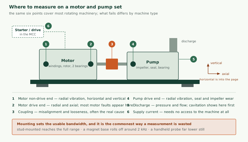
What actually fails
Before choosing sensors it is worth being clear about what goes wrong, because the intuitive answer is misleading. Bearings are what get replaced; they are frequently not what failed first.
A bearing in a correctly aligned, balanced, adequately lubricated machine running within its design load lasts a long time. Most bearings that fail early were loaded by something else: a misaligned coupling, an unbalanced rotor, a soft foot, a pump running off its curve, or contaminated lubricant. Monitoring that detects the bearing damage and stops there catches the symptom a few weeks before failure and leaves the cause in place, so the replacement fails the same way.
| Cause | Typical share | What sees it | Where it shows |
|---|---|---|---|
| Lubrication — wrong, insufficient, contaminated | Large, frequently the single biggest | Ultrasound, temperature, oil analysis | Bearing, before vibration changes |
| Misalignment | Very common on coupled sets | Vibration, twice running speed, high axial | Coupling and adjacent bearings |
| Imbalance | Common, worsens with fouling and wear | Vibration at running speed, radial | Both bearings, in phase |
| Looseness and soft foot | Common, often from installation | Vibration, harmonics of running speed | Feet, baseplate, vertical direction |
| Process conditions | Underestimated | Pressure, flow, current, temperature | Not at the bearing at all |
| Electrical faults | Motors specifically | Current signature, insulation testing | Invisible to vibration until late |
| Bearing defect as the primary cause | Smaller than assumed | Vibration, high frequency; ultrasound earlier | The bearing itself |
The practical consequence is that a programme built only around bearing detection is aimed at the smallest category. Measuring alignment-related and process-related conditions is frequently cheaper and prevents failures rather than anticipating them. This is also why recording what was found at each intervention matters so much: without it you cannot tell whether you are fixing causes or replacing symptoms.
Motors
An induction motor fails mechanically like any rotating machine and electrically in ways nothing mechanical will show you.
- Bearings — the commonest mechanical failure, detected by vibration at high frequency, and earlier by ultrasound where lubrication is the cause.
- Rotor bars — cracked or broken bars produce sidebands around the supply frequency in the current spectrum. Vibration shows this late and ambiguously; current shows it clearly.
- Stator winding insulation — degrades with thermal cycling and partial discharge. Online detection is limited; this is mostly a matter of temperature history and offline testing.
- Air gap eccentricity — from bearing wear or a bent shaft, visible in current and in vibration at twice line frequency.
- Bearing currents — where a variable-speed drive is fitted, common-mode voltage can discharge through the bearing and erode the raceway. This is a drive-installation problem, addressed with insulated bearings, shaft grounding or output filtering, and worth checking before assuming a bearing quality issue.
- Overheating — from overload, poor ventilation, or unbalanced supply. Winding temperature where an embedded sensor exists; otherwise frame temperature, which lags considerably.
Motor current signature analysis
Worth its own treatment because it is consistently underused. The measurement is taken at the starter or drive, usually in an electrical room, with a current transformer on one or more phases. Nothing is mounted on the machine.
That property is the point. For a motor that is hazardous to approach, inside a guard, submerged, at height, or simply cannot be stopped long enough to fit a sensor, current analysis may be the only route that does not require a shutdown and an access plan. We would raise it before anyone costs a scaffold.
What it sees well: rotor bar damage, eccentricity, load variation, supply imbalance, and mechanical looseness transmitted through the load. What it sees poorly: early bearing damage, and anything on the driven machine that does not modulate the load appreciably. It is also confounded by variable-speed drives, which is a real limitation — the drive’s own switching dominates the spectrum, and analysis either needs the drive’s internal data or a technique adapted for it. Ask specifically about this before specifying it on a drive-fed motor.
Pumps
Centrifugal pumps are the most numerous machines in most plants and the ones where process conditions cause more failures than mechanical wear.
| Failure mode | Cause | Best measurement | Warning available |
|---|---|---|---|
| Cavitation | Insufficient suction head | Suction pressure; broadband vibration; audible | Immediate if suction is measured, otherwise from damage |
| Running off the curve | Wrong duty, throttled discharge, system change | Discharge pressure with flow, or current as a proxy | Continuous, if the curve is known |
| Dry running | Loss of suction, closed valve | Current, temperature; both fast | Seconds to minutes. Needs automatic action, not an alert. |
| Seal failure | Dry running, misalignment, wear | Leak detection, temperature | Short, and the consequences may be environmental |
| Impeller wear or fouling | Abrasive or depositing fluid | Efficiency trend: pressure and flow against current | Months, if efficiency is trended |
| Bearing and seal-face wear | Normal, accelerated by the above | Vibration, temperature | Weeks |
The pattern worth noticing is that four of the six are best seen with process measurements rather than vibration. A pump programme built only on accelerometers detects the consequences of running off the curve without being able to see that it is happening. Adding discharge pressure, and flow where it is available, frequently costs less than the vibration sensing and prevents rather than predicts. Choosing those instruments is covered in tank level, cold chain and water quality monitoring.
Dry running deserves emphasis because it is the one condition where monitoring alone is insufficient. A pump can be destroyed in under a minute, which is shorter than any human response, so protection has to be automatic. That is a control function rather than a monitoring one, and treating it as an alerting problem is a design error.
Positive displacement pumps differ: they generate pressure regardless of the system, so the dominant risks are overpressure with a blocked discharge, valve wear in reciprocating types, and pulsation. Relief protection is a safety matter rather than a monitoring one.
Compressors
Compressors carry a higher energy cost than almost any other auxiliary, so efficiency monitoring frequently pays for itself before any failure is avoided.
Reciprocating compressors fail predominantly at the valves. Valve failure raises discharge temperature and reduces throughput, and both are cheap to measure. Vibration and ultrasound on the valve covers can identify which valve, which turns a shutdown into a targeted repair. Piston rings, rod packing and crosshead bearings follow, and rod drop monitoring is standard on large machines.
Screw compressors fail at bearings and at the rotor clearances, with oil condition central to both. Discharge temperature, differential pressure across the separator and oil condition cover most of it; vibration is useful but less dominant than on other machine types.
For both, two measurements carry most of the value and are routinely absent. Discharge temperature responds to most developing faults. And specific power — energy per unit of compressed air delivered — trends the machine’s actual condition in the units the business cares about. Air systems commonly waste a substantial fraction of their energy in leaks, and a system that measures delivered air against energy consumed finds that without any failure needing to occur. The wider treatment is in OEE and energy monitoring.
Fans, blowers and gearboxes
Fans are mechanically simple and fail mostly through imbalance, which develops as material deposits on or erodes from the impeller. Vibration at running speed in the radial direction detects it clearly, and the response is cleaning or balancing rather than replacement. Belt-driven fans add belt wear and tension, both of which produce characteristic vibration at belt frequency. Large fans mounted on flexible steelwork can also excite structural resonance, which looks alarming and is a mounting problem rather than a machine fault.
Gearboxes are the most demanding case. Faults appear as modulation around the tooth-mesh frequency, which requires both adequate bandwidth and knowledge of the gear ratios to interpret. A generic overall-level alarm on a gearbox is close to useless: significant tooth damage can develop with little change in overall vibration. Gearboxes are also where oil analysis earns its place most clearly, since wear particles identify which element is degrading and frequently give longer warning than vibration.
Slow-speed machinery generally — below a few hundred revolutions per minute — is a case where conventional accelerometers struggle, because the energy at those frequencies is low. Acoustic emission and specialised low-frequency sensing are the usual answers, and it is worth establishing this constraint before specifying rather than after the data proves uninformative.
Choosing the measurement
| Technique | Detects | Warning | Needs | Cost |
|---|---|---|---|---|
| Vibration, overall level | Imbalance, misalignment, looseness, late bearing | Weeks | Rigid mounting, a baseline | Low |
| Vibration, spectral | Which fault, and which element | Weeks to months | Bandwidth, machine geometry, an analyst | Medium to high |
| Ultrasound | Lubrication problems, early bearing, leaks | Months for lubrication | Technique discipline; often handheld | Low |
| Motor current signature | Rotor bars, eccentricity, load faults | Months | Access to the starter only | Low to medium |
| Temperature | Friction, overload, cooling loss | Short; confirms rather than predicts | Sensible placement | Very low |
| Oil analysis | Wear mode, contamination, oil condition | Months | Sampling discipline, a laboratory | Medium, recurring |
| Process measurements | The conditions that cause failure | Continuous | Knowing the expected relationship | Low where instruments exist |
Two observations. Ultrasound is the cheapest technique with the longest warning for the commonest cause of bearing failure, and it is frequently omitted because it does not produce a continuous data stream. And process measurements often already exist — a pump’s discharge pressure may be on the SCADA system, unrecorded — so the cost is integration rather than instrumentation. SCADA and PLC integration covers getting at it.
Mounting, which decides whether any of it works
The single most common way a vibration measurement is wasted is the mounting. The sensor’s usable frequency range is limited by how it is attached, and early bearing evidence lives at high frequency.
- Stud-mounted into a prepared flat face reaches the sensor’s full range. Required for bearing diagnosis.
- Adhesive pad is close to stud performance and much easier to retrofit. A sensible default.
- Magnet base typically rolls off around 2 kHz, which removes early bearing evidence. Acceptable for imbalance and alignment; not for what most people buy it for.
- Handheld probe is lower still and varies with operator pressure, so readings are not comparable between visits.
Placement matters as much. The sensor should be on the bearing housing, in the load zone, with as short and stiff a path to the bearing as possible — not on a cover, a fan shroud or a painted surface. A sensor on sheet metal measures the sheet metal. And the position must be repeatable, which in practice means a permanently marked or fitted location, because a reading taken 100 mm away is not comparable with last month’s.
Reading a spectrum without becoming an analyst
Full diagnostic analysis is a specialism and this section will not make anyone an analyst. But a maintenance engineer who understands four or five relationships can interpret a great deal, and more usefully can tell whether a supplier’s diagnosis is plausible.
Everything starts from the running speed. Convert it to hertz — divide revolutions per minute by 60 — and the important frequencies are multiples of it.
| Where the energy is | Usually means | Confirming evidence |
|---|---|---|
| 1× running speed, radial | Imbalance | Both bearings similar and in phase; rises with fouling |
| 2× running speed, with high axial | Misalignment | Axial comparable to radial, which is otherwise unusual |
| Many harmonics: 1×, 2×, 3×, 4×… | Looseness | Worst vertically, at the feet; check hold-down bolts first |
| Non-integer multiples, typically 2× to 12× | Bearing defect | Frequencies calculated from bearing geometry |
| Number of vanes or blades × running speed | Flow-related, normal at some level | Concerning only if it rises |
| Sidebands around a main peak | Modulation: gear or rotor bar faults | Spacing identifies the modulating frequency |
| Broadband, no clear peaks | Cavitation, severe wear, or looseness | On a pump, check suction conditions first |
| Twice line frequency, 100 or 120 Hz | Electrical, not mechanical | Disappears within a rotation of switching off |
The last row is worth knowing because it prevents a common misdiagnosis. Electrical vibration stops instantly when supply is removed; mechanical vibration decays as the machine coasts. Switching off while watching is a decisive and free test.
Bearing defect frequencies are calculated from the bearing’s internal geometry, which is why the bearing part number matters. Detecting a rise is possible without it; saying which element — inner race, outer race, rolling element or cage — is not. Suppliers who identify a specific bearing element without having the part number are guessing.
The machine information you will need
Gathering this before installation saves a return visit, and its absence is the commonest reason a first dataset cannot be interpreted:
- Running speed, and whether it varies. If the machine is on a variable-speed drive, everything above moves with it and the analysis must be order-based rather than frequency-based, which the sensing has to support.
- Bearing part numbers at each position. Frequently only in the original manual, and worth recovering before the manual is lost.
- Number of impeller vanes, fan blades or compressor lobes. Determines which peaks are normal.
- Gear ratios and tooth counts for any gearbox.
- Nameplate rating, and the actual duty. A motor running at 40% of rating behaves differently from one at 95%, and both are common.
- Foundation and mounting: rigid or flexible. It changes which ISO band applies.
- Maintenance history. What has failed, how often, what was found. This decides which failure modes are worth the money and is almost always more valuable than any technical specification.
Variable-speed drives deserve a second mention because they are increasingly common and they complicate everything here. Speed changes move every diagnostic frequency, so fixed-band alarms produce nonsense; the sensor or the analysis must track speed, either from the drive or by estimating it from the signal. If a supplier’s proposal does not mention this for a drive-fed machine, it is worth asking about directly.
Wireless in practice
Since installation dominates retrofit cost, wireless sensing is frequently the difference between a programme that happens and one that is priced and shelved. The trade-offs are specific enough to be worth stating.
| Wireless | Wired | |
|---|---|---|
| Installation | Hours, often without a shutdown | Days, usually needs one |
| Unit cost | Higher | Lower, plus cable and labour |
| Measurement rate | Periodic; full spectra sparingly | Continuous if wanted |
| Bandwidth | Often limited by power budget | Whatever the sensor supports |
| Maintenance | Battery replacement every few years | Effectively none |
| Suits | Trending across many machines | Diagnosis on a few critical ones |
The honest summary is that wireless is well matched to detection across a wide estate and poorly matched to diagnosis on a critical machine. A common and sensible arrangement is wireless breadth with wired sensing on the handful of machines where a failure genuinely stops the site.
Two practical points. Battery life quoted by vendors assumes a measurement interval; taking spectra hourly instead of daily can reduce a five-year life to months, and that is a configuration decision made after purchase. And metal environments are hostile to radio — a sensor inside a machine guard or a metal enclosure may not reach its gateway even at short range, which is a site survey question rather than a datasheet one.
Building plant and HVAC
Chillers, air handling units, pumps and fans in building services are rotating machinery like any other, and they are worth separate mention because the economics differ. Failure rarely stops production, so the case is usually made on energy and comfort rather than downtime.
- Air handling units fail through filter blockage, belt wear and fan imbalance. Differential pressure across the filter is a cheap and directly actionable measurement, and it replaces changing filters on a calendar with changing them when blocked.
- Chillers lose efficiency through fouled condensers, refrigerant loss and control problems long before anything fails. Approach temperatures — the difference between refrigerant and water temperatures — are the standard indicator and are usually already available in the chiller’s own controller.
- Cooling towers suffer fan gearbox wear, fill fouling and water treatment problems. Vibration on the fan drive is worthwhile; water quality frequently matters more.
- Pumps in building services are commonly oversized and throttled, which wastes energy continuously. Measuring differential pressure and flow against consumption identifies this, and the fix is a control change rather than a repair.
The recurring finding in building plant is that the largest savings come from equipment that is working correctly but running when it need not, or harder than it need. That is a controls and scheduling question that monitoring reveals rather than a maintenance one, and it usually pays back faster than failure avoidance. Much of the necessary data already exists inside the building management system and is simply not trended.
A worked example
To make the selection concrete, consider a plant with a cooling water pump set: a 75 kW motor driving a centrifugal pump through a flexible coupling, running continuously, with no installed spare. Failure stops production within the hour.
The maintenance history shows three failures in six years: two mechanical seals and one motor bearing. The seals were replaced reactively; the bearing was found during an unrelated inspection.
A generic approach would fit accelerometers to both bearings and trend overall level. That would probably have caught the motor bearing. It would not have caught either seal failure, which is where two of the three failures were.
Reading the history differently: seal failures on a cooling water pump usually follow from dry running, misalignment or running off the curve. So the specification becomes:
- Discharge pressure, trended against motor current. Together these locate the pump on its curve and reveal both throttling and impeller wear. Cheap, and frequently already on the SCADA system.
- Suction pressure, if there is any cavitation risk. Directly addresses a likely seal-failure cause.
- Motor current, which also gives dry-running detection — but with automatic shutdown rather than an alert, since the damage is faster than any human response.
- Vibration, adhesive-mounted, on the motor drive end and the pump drive end. Adhesive rather than magnet because bearing evidence is the point. Axial included at the coupling end for misalignment, given that misalignment is a plausible cause of the seal failures.
- Temperature at both bearings. Cheap, and confirms what vibration suggests.
- A recorded alignment check after any intervention — not monitoring at all, and possibly the highest-value item on the list.
The difference is not sophistication. It is that the second specification was derived from what had actually failed, and the first from what is conventionally fitted. That reading of the maintenance history is the work worth paying for.
Thresholds, and the standards
ISO 20816, which supersedes the widely cited ISO 10816, gives vibration velocity bands by machine size and mounting rigidity. ISO 13373 covers the wider practice, and ISO 18436 addresses personnel certification.
These are useful and frequently over-interpreted. The bands are necessarily broad because they describe classes of machine rather than yours. A machine can sit comfortably inside the acceptable band while its own vibration has tripled over six months, and that trend is far more informative than the absolute figure. Equally, a machine may sit permanently in a higher band because of its mounting without anything being wrong.
The workable approach is to use the standard’s bands as an initial alarm when you have nothing else, establish a per-machine baseline across the normal range of operating conditions, then alarm primarily on change from that baseline while keeping an absolute limit as a backstop. Baselining is where programmes are usually rushed: a baseline taken over a single week in summer will produce false alarms all winter, and one taken at a single load will misfire whenever the duty changes. We reference the standards for what they are and do not issue certifications against them.
What it costs, in shape
Per-machine figures depend on access, hazardous-area requirements and what infrastructure exists, which is why a survey precedes a quotation. The shape, however, is consistent and not where people expect.
| Item | Share | Notes |
|---|---|---|
| Sensors | 10 to 20% | What everyone budgets for |
| Installation and access | 25 to 40% | Dominated by shutdown windows and access equipment |
| Cabling or wireless infrastructure | 15 to 25% | Where wireless usually earns its premium |
| Integration and configuration | 15 to 25% | Getting data where decisions are made |
| Baselining and alarm setting | 10 to 15% | Elapsed time; cannot be compressed with more people |
| Ongoing review | Recurring | Small, and its absence is why programmes decay |
Installation dominating is why wireless is frequently worth its higher unit cost and shorter battery life: it converts a cabling project into a fitting task. The trade-offs are covered in choosing IoT connectivity and battery life. It is also why current signature analysis is attractive where access is difficult — the installation cost largely disappears.
Lubrication, which causes more failures than anything else
Given that lubrication problems are the largest single contributor to bearing failure, it deserves more than a row in a table — particularly because it is the area where cheap intervention displaces expensive monitoring most clearly.
The failure modes are four, and they are not interchangeable:
- Insufficient lubricant, from a missed interval or a blocked path. Produces rising friction and temperature, and ultrasound detects it earlier and more reliably than vibration.
- Excessive lubricant, which is at least as common and is usually the result of well-intentioned over-greasing. It churns, overheats, and can blow out seals. Measurably worse than slightly under-greasing.
- Wrong lubricant, or mixed incompatible greases, which can produce a soap that no longer lubricates at all.
- Contaminated lubricant, with water or particulate. Water is especially damaging and frequently arrives through breathers and seals rather than during filling.
Ultrasound is the appropriate instrument here and is under-used. A bearing starved of lubricant emits a rising high-frequency signature well before vibration or temperature responds, and greasing while listening lets an operator stop at the point the signature drops rather than delivering a fixed number of strokes. That single practice addresses both under- and over-greasing, needs no permanent installation, and costs less than instrumenting the same machines.
For oil-lubricated machinery — gearboxes, screw compressors, larger bearings — oil analysis serves the same purpose with longer warning. Sampling discipline determines whether it works: samples taken from a different point, or after a top-up, produce results that are not comparable, and inconsistent sampling is the usual reason a programme is abandoned as uninformative.
The wider point is that a good proportion of what monitoring is bought to predict would not occur under better lubrication practice. We would rather see a plant fix that first, and say so even where it means less to install.
Thermography, and where it fits
Thermal imaging is widely available and frequently misapplied to rotating machinery. It is excellent for electrical connections, where a loose or corroded termination heats measurably before it fails, and a switchgear survey is among the highest-value hours anyone can spend in a plant.
On rotating machines it is more limited. Surface temperature is an indirect and lagging indicator of a bearing problem: by the time the housing is measurably hot, the warning that vibration or ultrasound would have given has largely passed. It also requires line of sight, which guards and enclosures obstruct, and readings are strongly affected by surface emissivity — a painted housing and a bare metal one at identical temperatures will read differently, which is a frequent source of false conclusions.
Where it does earn its place on machines: finding cooling problems such as blocked motor fan covers or fouled cooling fins, checking couplings and belt drives, and comparing identical machines side by side, where relative differences are more reliable than absolute readings. Treat it as a survey tool complementing continuous monitoring rather than a substitute for it.
Choosing which machines, by type
Criticality assessment is covered in the predictive maintenance article. What is worth adding here is that machine type shifts the answer, because the warning available differs.
| Machine | Warning typically available | Monitor when | Probably not worth it when |
|---|---|---|---|
| Large motor, no spare | Weeks to months | Nearly always: long lead times on replacement | A shelf spare and a quick swap exist |
| Centrifugal pump | Months, if process conditions are measured | Duty-critical, or repeated seal failures | Installed spare with automatic changeover |
| Reciprocating compressor | Weeks; valves give good warning | Almost always: energy case stands alone | Small, redundant units |
| Screw compressor | Months through oil and temperature | Energy cost justifies it before failure does | Rarely — usually worth something |
| Fan | Months; imbalance develops slowly | Large, high, or process-critical | Small, accessible, spare available |
| Gearbox | Months with oil analysis; less with vibration alone | Long lead time or major access work | Small standard units held in stock |
| Slow-speed machinery | Poor with conventional sensing | Only with sensing suited to low frequency | Standard accelerometers will disappoint |
Two entries deserve emphasis. Compressors frequently justify monitoring on energy alone, independent of any failure avoided, which means the business case does not depend on predicting anything. And installed spares with automatic changeover genuinely weaken the case: if a failure causes no loss of production, the value is the repair cost difference rather than the downtime, which is a much smaller number and often below the cost of monitoring.
Conversely, lead time is consistently undervalued. A machine that would take fourteen weeks to replace justifies monitoring at a criticality that would not otherwise warrant it, because the warning converts an emergency into a planned procurement. Checking replacement lead times is a cheap piece of analysis that frequently reorders the priority list.
What usually goes wrong
- Instrumenting the easy machines. Accessible and uncritical is the wrong selection criterion, and it is the one that gets used when access drives the plan.
- Magnet-mounted sensors bought for bearing analysis. The bandwidth needed for the purpose is not there.
- Alarming on the standard rather than the machine. Produces false alarms on some machines and silence on others.
- Baselining too quickly. A baseline that does not span the normal range of load, product and season will misfire for a year.
- Ignoring the process measurements. On pumps and compressors these carry more information than vibration and frequently already exist.
- No recorded findings. Without what was actually found at each intervention, the data never becomes diagnostic and the programme cannot improve.
- Detection without a response path. An alert that reaches nobody with authority to act on it is an expensive way to generate a record that you knew.
Claims worth questioning
This is a field with confident marketing, and a few claims recur often enough to be worth testing before signing anything.
- “Detects any fault with one sensor.” No single measurement sees electrical faults, cavitation, lubrication problems and gear wear. Ask which failure modes it does not detect; a supplier who cannot answer has not thought about it.
- “AI, so no baseline needed.” Learning what normal looks like is baselining. The question is not whether a baseline is needed but how long it takes and what operating conditions it must span. Edge AI on microcontrollers covers what these models can and cannot do.
- “Predicts failure weeks in advance.” Sometimes true for some failure modes on some machines. Prediction of a specific failure needs history of that failure; a system with no such history is detecting abnormality, which is useful and is a different claim.
- “Reduces downtime by 30 to 50%.” Drawn from studies of plants that were running to failure with no maintenance programme. A plant already doing planned maintenance competently will see a much smaller change, and any figure quoted before seeing your records is a brochure number.
- “Install in minutes, no expertise required.” The installation may genuinely be quick. Interpreting the output, setting thresholds that neither cry wolf nor stay silent, and deciding what to do about an alert all require expertise, whether yours or someone’s.
- “Works on any machine.” Slow-speed machinery, variable-speed drives and highly variable duties each break assumptions that most products embed. Ask specifically about yours.
A reasonable test of any supplier, ourselves included: ask what their system will not detect, and what would make them advise against installing it. An answer that names real limits is worth more than one that names none.
How we help with this
We work on the engineering side of condition monitoring: deciding what to measure for the failure modes that actually matter on your machines, selecting sensors and mounting, designing the installation and data path into whatever you already run, and setting up baselining and alerting so that what arrives is actionable.
We would start by looking at the machines and your maintenance history, because which failures are worth catching is a question your records answer and nobody can answer from outside. We do not certify machines as fit for service, we do not diagnose faults remotely without machine history and geometry, and we would not quote a downtime reduction before seeing the equipment.
Related reading: predictive maintenance and what it takes for the programme around this, sensor selection for the measurement chain, retrofitting legacy machines where there is no controller to read, and OT/IT integration for connecting findings to the maintenance system. Services: industrial IoT integration. For the wider picture, what industrial IoT actually is.
If you take one thing away
Start from what has actually failed on your machines rather than from what is conventionally fitted. A maintenance history showing repeated seal failures points at process conditions; one showing motor bearings points somewhere else entirely, and the two lead to different sensors in different places.
That reading takes an afternoon with your records and a walk around the plant. It routinely changes the specification more than any choice between sensor vendors, and it is the step most often skipped in favour of ordering hardware.
Questions we are asked about this
What clients ask before starting
Which machines are worth monitoring?
Ones where failure is expensive and gives warning. A large motor driving a process with no spare is an obvious candidate; a small fan with a shelf spare and a five-minute swap is not, however easy it would be to instrument. The test is what a week of warning would actually be worth, and for a great many machines the honest answer is very little.
Is vibration always the right measurement?
It is the most informative for bearings, imbalance, misalignment and looseness, which covers most mechanical failure. It is poor for electrical faults in motors, for cavitation in its early stages, and for anything on a slow-turning shaft. Current signature analysis, pressure and temperature each see things vibration does not, and the sensible approach is to choose per failure mode rather than fitting accelerometers everywhere by default.
Can we monitor a motor without touching it?
Often yes. Motor current signature analysis measures the supply current at the starter, which is usually in an electrical room rather than on the machine, and it detects rotor bar damage, some bearing faults and load abnormalities. For machines that are hard to reach, hazardous or cannot be stopped for sensor fitting, it is frequently the only practical route and it should be considered before an access scaffold is costed.
What about the ISO vibration limits?
ISO 20816 gives broad velocity bands by machine size and mounting, and they are a reasonable starting point when you have nothing else. Their weakness is that they are general: a machine can sit inside the acceptable band while its own vibration has tripled, which is the more meaningful signal. Use the standard to set an initial alarm and replace it with a per-machine baseline as soon as you have one.
How long before we see anything useful?
Detecting a departure from normal needs a baseline, so typically a few weeks of running across the normal range of conditions. Identifying which fault is developing needs either an analyst or accumulated history with recorded outcomes, which takes considerably longer. Anyone promising specific failure prediction in the first month is describing something other than what will happen.
Do we need an analyst?
For interpreting spectra and diagnosing a specific fault, yes, at least available to you. Overall level trending and alerting on change can be run without one and catches a useful proportion of developing problems. A reasonable arrangement is automated monitoring for detection with a specialist called in when something changes, rather than a specialist on a route schedule.
Is wireless good enough?
For trending overall levels and temperature, generally yes, and it removes most of the installation cost. For high-resolution spectral analysis the constraints are real: battery life limits how often a full spectrum can be taken, and the sampling bandwidth is usually lower. Wired sensing remains preferable on critical machines where diagnosis rather than detection is the point.
What do you actually provide?
Sensor and measurement selection for the failure modes that matter on your machines, mounting and installation design, the data path into whatever you already run, baselining and alert configuration, and documentation of what was fitted and why. We do not certify machines as fit for service, we do not diagnose faults remotely without the machine history, and we would not quote a downtime reduction before seeing the equipment and your maintenance records.
Which machine causes you the most trouble?
Tell us what the equipment is, what has failed on it before and what a failure costs when it happens. That is usually enough to say whether monitoring would have caught it.