
Machine vision for inspection: what actually decides whether it works
Lighting decides more than the camera, a fixture beats software for presentation variation, and defining the defect precisely is harder and more important than choosing an algorithm.
In short
- Lighting decides more than the camera. Get it right and the algorithm becomes simple; get it wrong and nothing rescues it.
- Presentation consistency is the second factor. A fixture is often cheaper than the software to cope without one.
- Classical methods beat machine learning for geometrically definable defects on consistently presented parts.
- Define the defect precisely first. If people disagree about what is acceptable, no system can be correct.
- False rejects and false accepts cost differently. Which matters decides where the system is tuned.
What vision is genuinely good at
Camera-based inspection does some things exceptionally well and others poorly, and the difference is worth establishing before a project is scoped.
It excels at consistency. A camera checks every part identically, at line speed, without fatigue, on the night shift as on the day shift. Where a human inspector’s judgement drifts across a shift and differs between people, a vision system applies the same criterion every time.
It is good at measurement, at detecting presence and absence, at counting, at checking orientation, and at finding defects that alter appearance in a consistent way. It is poor at anything requiring judgement about whether a deviation matters, at defects that look different every time, and at anything a person identifies partly by feel or sound.
The useful framing: vision replaces inspection tasks that are tedious and objective. It does not replace an experienced operator’s judgement, and projects that promise it will tend to disappoint.
Lighting, which decides everything else
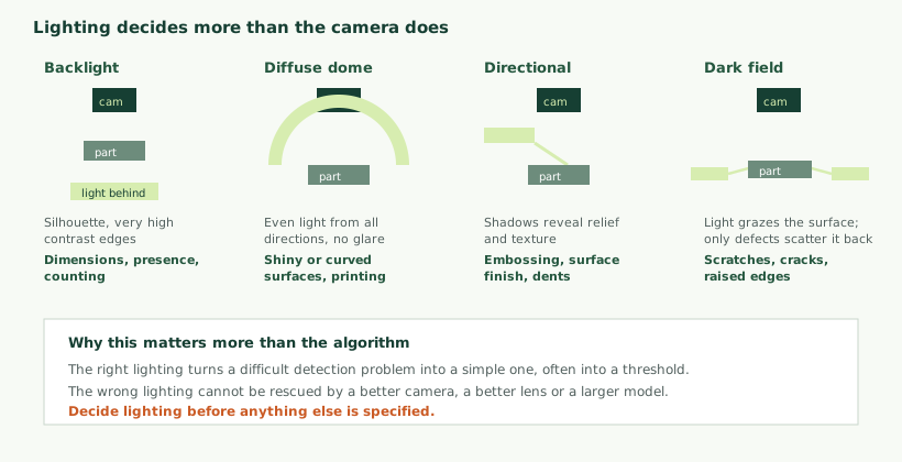
If there is one thing to take from this article, it is that lighting is the dominant variable and it is chosen first, before the camera, the lens or the software.
Backlighting places the light behind the part so the camera sees a silhouette. Contrast is extremely high and the resulting image is close to binary, which makes dimensional measurement, presence checking and counting straightforward. Where the feature of interest is an outline, this is almost always the right answer.
Diffuse dome lighting surrounds the part with light arriving from all directions, which eliminates the specular highlights that make shiny and curved surfaces difficult. It suits reading printing on reflective packaging and inspecting polished parts.
Directional lighting at an angle produces shadows, which reveal relief: embossing, engraving, surface texture and dents. The same feature that is invisible under even illumination becomes obvious.
Dark field lighting grazes the surface at a very low angle so that a flat surface reflects nothing toward the camera and appears dark, while scratches, cracks and raised edges scatter light back and appear bright. For surface defect detection this is frequently transformative.
Coaxial lighting delivers light along the camera’s own axis, which suits flat reflective surfaces where you need to see markings without glare.
Two further points. Ambient light is the enemy: a system that works during the day and fails at night, or vice versa, is usually being affected by room lighting or daylight, and enclosing the inspection station is cheaper than compensating in software. And strobing both freezes motion and overwhelms ambient light, which is why it is common on moving lines.
Optics, briefly but consequentially
The lens determines what the sensor actually sees, and several relationships constrain the design together rather than independently.
- Field of view and working distance determine the focal length required. Fixing two of these fixes the third, so the mechanical space available is a genuine constraint on the optical design.
- Resolution must be sufficient for the smallest feature. A defect spanning one pixel is indistinguishable from noise. Several pixels across the smallest feature you must reliably detect is the realistic requirement, and working backwards from that gives the sensor resolution rather than choosing a camera and hoping.
- Depth of field determines how much variation in part height remains in focus. A smaller aperture increases it and admits less light, which is one of several reasons lighting and optics are chosen together.
- Perspective error affects dimensional measurement: parts nearer the lens appear larger. Where accurate measurement matters, telecentric lenses remove this at the cost of being physically larger and more expensive, and being limited to objects smaller than the lens.
- Distortion at the edges of wide-angle lenses affects measurement and can be calibrated out, provided somebody remembers to do it.
Choosing the camera
Camera selection follows from the lighting, the optics and the motion, rather than leading them.
Shutter type matters when anything moves. A rolling shutter exposes the sensor progressively, so a moving object is captured at slightly different times across the frame and appears distorted. For a stationary part this is irrelevant; for a part on a conveyor it produces measurement errors that are difficult to attribute. Global shutter exposes the whole sensor at once and is the correct choice for motion.
Monochrome is usually better unless colour is the point. A colour sensor obtains colour by filtering individual pixels, which reduces effective resolution and sensitivity. Where the inspection does not depend on colour, a monochrome sensor of the same specification gives a sharper, more sensitive image. Choosing colour by default gives away performance for nothing.
Interface and frame rate follow from throughput: how quickly images must be captured and transferred, and whether the processing can keep up.
Line-scan cameras suit continuous material such as web or strip, building an image line by line as the material moves. They require careful synchronisation with motion and are a different discipline from area-scan inspection.
Calibration, and what it is for
Calibration means different things in vision depending on what the system is doing, and confusing them causes real problems.
Spatial calibration establishes the relationship between pixels and real-world units, so a measurement in the image becomes a measurement in millimetres. It requires a known artefact imaged under the same conditions as production parts, and it has to be repeated when anything optical or mechanical changes. A system reporting dimensions without this is reporting pixels dressed up as measurements.
Distortion correction compensates for the lens bending straight lines, which matters most toward the edges of the field of view. Without it, a part measured at the centre and the same part measured at the edge give different answers, which appears as inconsistency in the process rather than in the instrument.
Coordinate calibration relates what the camera sees to where a machine must move, which is what makes vision-guided handling possible. This is a more demanding exercise than measurement calibration and is usually where guidance projects spend their time.
Reference standards for defect judgement. Where the system judges appearance rather than dimensions, the equivalent of calibration is a set of physical reference parts spanning acceptable and unacceptable, retained and passed through periodically. This is what detects drift in a system where there is no measurable quantity to check.
In every case the important discipline is repeating it on a schedule rather than only at commissioning. A calibration performed once, on a system that has since been cleaned, knocked, relamped or had its product changed, is a record of how things used to be.
Presentation: the fixture is part of the system
The second-largest factor after lighting is how consistently the part arrives in front of the camera.
A part that is always in the same position, at the same orientation, at the same distance, presents the software with an almost trivial problem. A part that arrives anywhere in the field of view, at any rotation, at varying height, requires the software to find it, orient it and compensate before any inspection begins, and every one of those steps can fail.
Mechanical fixturing is frequently the cheapest improvement available in a vision project. A guide, a locating feature or a simple jig that constrains the part costs little and removes an entire category of software complexity, along with the failures that complexity brings.
This is the most common finding when a struggling vision project is reviewed: the answer is not a better algorithm but a fixture and a lamp.
The applications that recur
Most industrial vision work falls into a small number of shapes, and recognising which one you have narrows the design considerably.
| Task | Usual lighting | Approach | Main difficulty |
|---|---|---|---|
| Presence and absence | Backlight or directional | Classical, often trivial | Rarely difficult; a good first project |
| Dimensional measurement | Backlight, telecentric where accuracy matters | Classical | Calibration and perspective error |
| Orientation and position | Backlight or diffuse | Classical pattern matching | Symmetrical parts with ambiguous orientation |
| Counting | Backlight | Classical | Touching or overlapping items |
| Reading codes and text | Diffuse or coaxial | Dedicated libraries | Contrast on reflective or curved surfaces |
| Surface defects | Dark field or directional | Classical if definable, otherwise learned | Deciding what counts as a defect |
| Assembly verification | Diffuse | Classical, region by region | Many small checks, each able to fail |
| Colour and finish | Controlled diffuse, stable colour temperature | Classical measurement or learned | Lighting stability and calibration |
Two observations from that table. First, backlighting appears repeatedly, which reflects how much easier a silhouette is to work with than a reflected image. Where the inspection can be arranged to use it, a great deal of difficulty disappears.
Second, the rightmost column is more often organisational than technical. Touching items, ambiguous orientation and undefined defect criteria are problems of how parts arrive and what has been agreed, not problems of image processing, and they are usually cheaper to solve upstream.
Classical methods or machine learning
| Aspect | Classical methods | Machine learning |
|---|---|---|
| How it works | Explicit rules: thresholds, edges, shapes, measurements | Learns appearance from labelled examples |
| Needs | Consistent presentation and lighting | Representative labelled images across real variation |
| Behaviour | Deterministic and repeatable | Statistical; confidence rather than certainty |
| Explainability | The decision can be traced to a measurement | Harder to justify a specific verdict |
| Speed | Usually very fast | Depends on model and hardware |
| Handles variation | Poorly; breaks when conditions shift | Well, if the variation was in the training data |
| Best for | Dimensions, presence, orientation, counting, defined defects | Cosmetic defects, natural materials, appearance that varies |
The default should be classical. Where a defect can be described geometrically and parts are presented consistently, classical methods are faster, cheaper, explainable and far easier to validate. They also fail in understandable ways, which matters when something changes on the line.
Machine learning earns its place where appearance varies in ways rules cannot capture: natural materials, surface finishes with acceptable variation, cosmetic judgements. The considerations there, including data requirements and evaluation, are covered in edge AI and AI-enabled IoT development, and they apply directly.
A hybrid is common and often best: classical methods locate the part and isolate the region of interest, and a model judges the appearance within it. That reduces what the model must learn and keeps the geometric work deterministic.
When a camera is not the answer
Part of scoping honestly is recognising the cases where vision is the wrong tool, and several recur often enough to name.
- The defect is not visible. Internal voids, subsurface cracks, incorrect material, contamination that does not alter appearance. Other methods exist for these, including ultrasonic, radiographic and electrical testing, and a camera will not find them however good the lighting.
- The property is mechanical. Torque, force, stiffness, leak-tightness. These are measured directly, and attempting to infer them from appearance produces an unreliable proxy.
- The judgement depends on context a camera lacks. Whether a mark matters may depend on where the part will be used or what the customer has specified, which is information the image does not contain.
- The rate of occurrence is too low to justify it. A defect appearing once a year may not warrant a permanent inspection station, particularly if it is caught downstream at modest cost.
- The root cause is addressable. Where a defect arises from a known process problem, fixing the process removes the need to inspect for it. Automated inspection of a fault you could eliminate is a durable cost covering a fixable problem.
That last one deserves particular attention. Inspection detects; it does not improve. A system that catches a recurring defect reliably is preventing bad parts reaching customers, which is valuable, and it is not the same as producing fewer bad parts. Where the data from the inspection is fed back into understanding why the defect occurs, it becomes a process improvement tool, which is usually where the larger return sits.
Defining the defect, which is harder than it sounds
Before any system can be built, somebody has to say precisely what is acceptable, and this is where projects most often stall.
The test is simple and revealing: take a set of borderline parts and ask several experienced people to sort them into pass and fail independently. Disagreement between them sets a ceiling on what any automated system can achieve, because the system is being asked to reproduce a judgement that is not consistent in the first place.
Where that disagreement exists, resolving it is the first task, and it is an organisational one rather than a technical one. A written definition with reference samples, agreed by the people who own quality, is what makes the rest possible. It is also frequently valuable on its own, independent of any vision system.
The related question is whether the defect is even visible in an image. Some are detectable only by touch, by sound, by weight or by function, and no camera will find them. Establishing this early prevents a project that was impossible from the start.
Getting the trade-off right
Every inspection system sits between two errors: rejecting good parts and accepting bad ones. Moving the threshold trades one for the other, and no setting eliminates both.
These rarely cost the same. A false accept on a safety-related component may be unacceptable at any rate, which justifies rejecting a substantial number of good parts. A false reject on a low-value item with high production volume is simply waste, and tolerating a few escapes may be cheaper. The right operating point follows from that comparison, and it is a business decision rather than a technical one.
Two practical notes. The system should be validated against parts it has never seen, including real defective examples, not against the images used to configure it. And a run of known reference parts, both good and defective, passed through periodically, is what confirms the system is still behaving as it did on the day it was commissioned.
Data and training for learned approaches
Where machine learning is genuinely warranted, the project becomes a data project, and the same principles apply as in any other industrial application of it.
Defective examples are the constraint. Good parts are abundant; defective ones are rare, which is the point of making them rare. A dataset with thousands of good images and a dozen defective ones cannot train a model to recognise defects reliably. Collecting defects takes time, sometimes requires deliberately producing them, and is usually the longest part of the schedule.
Anomaly detection sidesteps this. Training only on good parts, and flagging anything that departs from that, needs no defective examples. It will flag genuine defects and also legitimate variation, so it produces a review queue rather than a verdict. For a first system on a line with no defect history, this is frequently the practical starting point.
Capture the variation that exists. Different batches of material, different suppliers, different times of day, different operators loading the machine. A model trained on one week of one batch learns that week.
Split by session, not at random. Images from the same production run are more similar to each other than to images from a different run. Splitting them randomly produces a model that appears excellent and does not survive a new batch, for the same reason described in edge AI on microcontrollers.
Labelling has to be consistent. If the people labelling images disagree, the model learns the disagreement. This connects directly to defining the defect, and it is why that definition has to come first.
Plan for retraining. Products change, materials change, and a model that was accurate at commissioning drifts. Keeping the images, keeping the labelling convention, and having a route to retrain and redeploy is what makes the system maintainable rather than a one-off.
Integration with the line
An inspection result is only useful if it arrives in time to act on the part it describes.
- Triggering. The camera must capture at the right moment, driven by a sensor or an encoder rather than by a timer, because line speed varies.
- Timing budget. Exposure, transfer, processing and the decision must all complete before the part reaches the point where it can be diverted. Working backwards from the reject mechanism gives the time available, which then constrains the processing.
- Tracking. On a line where several parts are in transit between inspection and rejection, the system must know which result belongs to which part. This is a common source of a system that rejects the wrong item.
- Interfacing to the controller. The verdict usually goes to a PLC, which operates the reject mechanism. Protocol, timing and what happens on a communication failure all need deciding; see SCADA and PLC integration.
- Failure behaviour. What the line does if the vision system stops. Continuing unchecked, stopping, or diverting everything are all defensible, and the choice should be deliberate.
- Recording. Keeping images of rejects, and a sample of accepts, is what allows a later dispute to be investigated and the system to be improved.
Where the processing runs
Inspection is one of the clearest cases for keeping computation local, because the result must arrive in time to act on the part that produced it. A round trip to a remote service does not fit inside a line cycle, and a network interruption would stop production.
| Option | Suits | Limits |
|---|---|---|
| Smart camera | A single self-contained check; compact installation; fewer parts to fail | Fixed processing capability; limited flexibility; awkward for several cameras |
| Industrial computer | Several cameras, heavier processing, machine learning, complex logic | More hardware to install and maintain; needs a cabinet |
| Computer with an accelerator | Learned models at line speed, higher resolution | Cost, power, thermal management in an enclosure |
| Central server on site | Many stations sharing resources; easier to update | Network becomes critical; latency needs care |
| Remote or cloud | Analysis of stored images, retraining, reporting | Not for in-line decisions |
A common and sensible arrangement is local processing for the decision, with images and results forwarded to a central system for storage, reporting and retraining. That keeps the line independent of the network while still accumulating the record that makes improvement possible, along the lines described in cloud backends and dashboards.
Storage, which adds up quickly
Images are large and a line generates them continuously. Keeping every image from every part is rarely justified and rarely affordable. The usual arrangement keeps all rejects, because those are what get disputed and investigated, a sampled proportion of accepts for reference and retraining, and everything for a short recent window so that an issue noticed today can be examined.
Deciding this before commissioning matters, because storage filling unexpectedly is a common cause of a vision system stopping.
What it costs, and where the effort goes
The distribution of effort in a vision project is consistently different from what people expect, which matters when scoping one.
Feasibility and lighting trials are modest in cost and decide the project. Skipping this stage to save time is the most expensive economy available here, because everything specified afterwards depends on conclusions that were never tested.
Hardware is usually a smaller share than anticipated. Cameras, lenses and lighting for a single station are rarely the dominant cost unless the application demands unusual resolution or speed.
Mechanical work is frequently underestimated: mounting, fixturing, enclosing the station to exclude ambient light, and the reject mechanism if one is needed. This is real engineering and fabrication, and it often exceeds the vision hardware.
Software and configuration varies enormously with the difficulty of the detection. A presence check is a day; a cosmetic defect judgement on a variable surface is a project.
Integration and commissioning covers triggering, timing, controller interfacing and the parallel running period. It is rarely quick, and it is where a schedule slips if the line is only available in windows.
Ongoing effort is the part most often omitted from a budget: cleaning optics, checking references, adjusting for product changes and retraining where a learned model is involved. A system with nobody responsible for it degrades, as described above.
The pattern is that the physical and organisational work outweighs the imaging work. A project plan that allocates most of its time to software is usually a plan that has not accounted for fixturing, ambient light exclusion and the parallel running period.
Keeping it working
Vision systems degrade quietly, and the degradation looks like a change in product quality unless somebody is watching for it.
Optics foul. Dust, coolant mist and fingerprints accumulate on a lens or window, reducing contrast gradually. Lighting ages, with output falling over thousands of hours. Cameras shift, particularly where mounted on equipment that vibrates. Products change, as suppliers alter a material or a process drifts. Any of these moves the system away from the conditions it was configured for.
The defences are straightforward: monitor image brightness and contrast as a proxy for lighting and optics condition, pass reference parts through periodically and check the results, and treat a rising reject rate as a system question before it is treated as a quality question. A cleaning schedule for optics is unglamorous and prevents a slow slide that is otherwise noticed only when it has become a problem.
Running a vision project so it succeeds
The sequence matters more in vision than in most engineering work, because the early stages determine whether the later ones are possible at all.
- Get samples first. Real parts, good and defective, in the range of variation production actually produces. Nothing useful can be decided without them, and obtaining defective examples is frequently the longest lead item.
- Do a lighting trial. Before any hardware is specified, establish which arrangement makes the feature visible. This can be done on a bench with borrowed equipment in a day, and it determines everything that follows.
- Agree the defect definition with the people who own quality, in writing, with reference samples.
- Prove feasibility on images before committing to installation. If the defect cannot be detected reliably in captured images under controlled conditions, it will not be detected on a moving line.
- Then specify the hardware, which by this point is largely determined.
- Install and calibrate, with attention to fixturing and ambient light exclusion.
- Validate against unseen parts, including deliberately introduced defects, and record the result as a baseline.
- Run in parallel with existing inspection before relying on it, comparing verdicts and investigating every disagreement. This is the step most often skipped and the one that builds trust.
That last point deserves emphasis. A period during which the vision system runs alongside human inspection, with disagreements examined rather than dismissed, finds the cases nobody anticipated and establishes whether the system is actually better. Switching directly from manual to automated inspection without it is how a line acquires a quality problem nobody can explain.
What to ask a supplier
- What lighting will you use, and why that? A supplier who has not decided this has not thought about the problem.
- Can you show it working on our actual parts? Including the borderline ones.
- What resolution, and what is the smallest defect that gives?
- What happens to throughput if the line speeds up?
- How will we know if it drifts?
- What will it not detect? A clear answer is a good sign.
- Who retrains or reconfigures it when the product changes?
Three worked situations
Checking that a component is present and correctly oriented
A straightforward case and a good first project. Backlighting or diffuse lighting depending on whether the outline or the face carries the information. A fixture holding the assembly in a repeatable position, which removes the need to locate it in software. Classical pattern matching against a reference, with a measurement confirming orientation. Processing is trivial, the decision is deterministic, and the system can be explained to anyone who asks why a part was rejected.
The likely difficulty is not detection but a symmetrical component whose correct orientation is ambiguous from one view, which may require a second camera or a feature that breaks the symmetry.
Measuring a dimension to a tight tolerance
Backlighting for maximum edge contrast, and a telecentric lens if the tolerance is tight enough that perspective error matters. Resolution chosen so the tolerance band spans a useful number of pixels rather than one or two. Careful calibration against a known artefact, repeated periodically, because a measurement system that has drifted reports confidently wrong numbers.
The likely difficulty is thermal: both the part and the fixture change dimension with temperature, and a measurement accurate to tight tolerances needs either a controlled environment or compensation.
Finding cosmetic defects on a variable surface
The hardest of the three and the one most often underestimated. Dark field or directional lighting to make surface irregularities visible. A precise written definition of what constitutes a defect, agreed in advance, with reference samples. Probably a learned approach, because the defects vary in appearance, which makes it a data project with the collection difficulty described above.
The likely difficulty is that the acceptable variation in the surface overlaps with what counts as a defect, which is a quality definition problem rather than a vision one. Where experienced inspectors disagree about borderline parts, that disagreement has to be resolved before the system can be judged, and frequently the most valuable output of the project is the agreed standard rather than the camera.
Mistakes worth avoiding
- Choosing the camera first. Lighting and optics determine what the camera needs to be.
- Solving presentation variation in software. A fixture is usually cheaper and more reliable.
- Ignoring ambient light. Systems that work by day and fail by night are common and avoidable.
- Insufficient resolution for the smallest defect. No processing recovers detail that was never captured.
- Rolling shutter on moving parts. Produces distortion that is difficult to attribute.
- Colour by default. Gives away resolution and sensitivity unless colour matters.
- Starting before the defect is defined. If people disagree, no system can be right.
- Validating on the configuration images. Tells you nothing about new parts.
- No drift monitoring. Degradation looks like a quality change.
How we help
- Feasibility. Establishing whether the defect is visible at all, and under what lighting, before hardware is committed.
- Lighting and optics design. Selecting the arrangement, testing it on real parts including real defects.
- Camera and hardware selection, driven by the optical and timing requirements.
- Software. Classical inspection, machine learning where it is warranted, or a hybrid.
- Integration. Triggering, timing, part tracking, controller interfacing and defined failure behaviour.
- Validation and monitoring. Testing against unseen parts, and the reference-part routine that keeps it honest.
Related work is described in AI for industrial machinery and industrial product development.
Beyond inspection: the other things cameras do
Inspection is the most common industrial application and not the only one. Several others use the same lighting, optics and presentation principles.
- Guidance. Locating a part so a robot or machine can act on it, which removes the need for precise fixturing elsewhere. The accuracy requirement is usually more demanding than for inspection, and calibration between the camera’s coordinates and the machine’s becomes the central problem.
- Identification. Reading codes or text to track a part through a process, which connects vision to production records and traceability.
- Measurement for process control. Feeding dimensions back to adjust a machine rather than only accepting or rejecting the result. This turns inspection from a filter into a control input and is frequently where the larger value sits.
- Counting and flow monitoring. How much is moving through a point, which overlaps with the utilisation measurement discussed in measuring OEE and energy.
- Safety-adjacent monitoring. Detecting presence in an area, with an important caveat: standard vision is not a safety device. Safety functions use certified equipment designed and approved for the purpose, and a camera system should not be relied upon to protect people.
The last point is worth stating plainly, because it recurs. A vision system can usefully observe and inform, and it should not be placed where its failure to detect something causes harm. That boundary is drawn at the start of an engagement, as with the analysis discussed in AI for industrial machinery.
A short glossary
| Term | Meaning |
|---|---|
| Field of view | The area the camera sees at the working distance. |
| Working distance | The distance from lens to part. |
| Depth of field | The range of distances that remain acceptably in focus. |
| Telecentric lens | A lens with no perspective error, so object size does not change with distance. Used for accurate dimensional measurement. |
| Global shutter | A sensor exposing all pixels simultaneously, required for moving objects. |
| Rolling shutter | A sensor exposing progressively, which distorts moving objects. |
| Backlight | Illumination from behind the part, producing a high-contrast silhouette. |
| Dark field | Illumination at a very low angle, so only surface irregularities scatter light back to the camera. |
| Coaxial lighting | Illumination along the camera axis, for flat reflective surfaces. |
| False accept | A defective part passed as good. |
| False reject | A good part discarded as defective. |
| Trigger | The signal causing the camera to capture, usually derived from part position rather than time. |
If you take one thing away
The order in which a vision project is approached determines whether it succeeds. Teams that start by choosing a camera and then try to make the images work spend the project fighting the physics. Teams that start with lighting, presentation and a precise definition of the defect usually find the remaining work straightforward.
That order is also the cheap one. A lighting trial on a bench costs a day. A fixture costs very little. An agreed written defect definition costs a meeting. All three happen before any hardware is bought, and together they determine most of the outcome.
The corollary is worth stating too: when a vision project is struggling, the answer is more often a lamp, a jig or a conversation about acceptance criteria than a better algorithm. Where inspection forms part of a production line, the wider build and test sequence is the context it sits in. For where inspection sits among the other applications of this data, see what industrial IoT actually is.
Questions we are asked about this
What clients ask before starting
What matters most in a vision system?
Lighting, by a considerable margin. The right arrangement turns a difficult detection problem into a simple one, frequently into a threshold. The wrong one cannot be rescued by a better camera, a better lens or a larger model.
Do we need machine learning for inspection?
Often not. Where parts are presented consistently and the defect is geometrically definable, classical methods are faster, deterministic, explainable and easier to validate. Machine learning earns its place where appearance varies in ways that cannot be described by rules.
How much resolution do we need?
Enough that the smallest feature you must detect spans several pixels, not one. A single pixel of difference is indistinguishable from noise. Working backwards from the smallest defect and the field of view gives the requirement, rather than choosing a camera first.
Why do systems that work in a demonstration fail in production?
Usually because the demonstration had controlled conditions that production does not: consistent part position, clean optics, stable lighting and a narrow range of product variation. The gap between those two situations is where most vision projects fail.
What is the difference between a false reject and a false accept?
A false reject discards a good part; a false accept passes a defective one. They almost never cost the same, and which matters more should decide where the system is tuned. A supplier who does not ask which you care about has not understood the problem.
Can we inspect parts that are moving?
Yes, with a global shutter camera and an exposure short enough to freeze the motion, or with strobed lighting. A rolling shutter camera will distort a moving object, which produces measurement errors that are difficult to diagnose.
How do we stop it drifting over time?
By expecting drift and designing for it: monitoring lighting output, checking optics for fouling, verifying camera position, and passing known reference parts through periodically so a shift is detected rather than gradually accepted.
Where should the processing run?
A smart camera suits simple, self-contained checks. An industrial computer suits several cameras, heavier processing or machine learning. Processing on site rather than remotely is almost always right for inspection, because the result has to arrive in time to act on the part.
What needs checking?
Tell us what the part is, what defect or measurement matters, how fast the line runs, and whether you have examples of both good and defective parts.