
EMC and compliance: designing electronics to pass rather than hoping to
Where emissions actually come from, why cables are usually the antenna, what pre-compliance can and cannot establish, and how to arrive at a test house prepared to fix things.
In short
- Most emissions problems are created at layout and cost nothing to avoid there. Fixing them afterwards means a new board; see PCB design in practice.
- Cables are usually the antenna, not the board. Interface filtering earns its place.
- Design for margin, not for passing. A product that just scrapes through has no room for a component change.
- Pre-compliance is not compliance, but it finds the obvious problems while they are still cheap.
- We prepare products for testing and support it. Compliance is established by accredited testing, and the declaration is the manufacturer’s.
The expensive way to find out
A product is designed, boards are made, units are assembled, and the whole thing is booked into a test house. It fails radiated emissions at a handful of frequencies. The cause turns out to be a layout decision, so the fix is a new board revision, new assembly, and another test slot several weeks later. The launch date moves and everybody is unhappy.
This sequence is common and largely avoidable. The great majority of emissions problems originate in decisions taken during schematic and layout: how return currents are routed, where the switching converter sits, how cables enter and leave, how the enclosure relates to the board. Those decisions cost nothing extra when taken deliberately and a great deal when revisited.
What follows is the practical shape of that: what the testing covers, where the problems come from, and what to do about them while it is still cheap.
What the testing actually covers
Two families of test, addressing opposite concerns: what your product emits, and what it tolerates.
| Test | Checking | Typical cause of failure |
|---|---|---|
| Conducted emissions | Noise your product puts back onto its supply | Switching converter, inadequate input filtering |
| Radiated emissions | Noise your product broadcasts | Loop area, fast edges, common-mode current on cables |
| Electrostatic discharge | Survival of a static discharge to accessible surfaces | No protection at exposed interfaces, poor grounding |
| Radiated immunity | Correct operation in a strong external field | Sensitive analogue inputs, long unfiltered cables |
| Conducted immunity | Correct operation with interference injected on cables | Same, usually at lower frequencies |
| Fast transients | Survival of bursts on supply and signal lines | Inadequate filtering, poor supply decoupling |
| Surge | Survival of large transients from switching or lightning | No surge protection on mains or long cables |
| Supply interruptions | Behaviour through dips and brief outages | Insufficient holdup, no defined restart behaviour |
Two things about this table are worth noting. First, immunity failures are frequently more disruptive to diagnose than emissions failures, because the symptom is a product that misbehaves rather than a measurement that is too high, and reproducing it outside the chamber can be awkward. Second, the limits differ considerably depending on whether a product is intended for industrial or residential environments, with residential limits generally stricter. Establishing which applies is an early decision, not a late one, because designing to the wrong one in either direction is costly.
Where emissions come from
Almost all of it reduces to one idea: a changing current flowing around a loop radiates, and how much depends on the area that loop encloses, how fast the current changes, and the frequency involved.
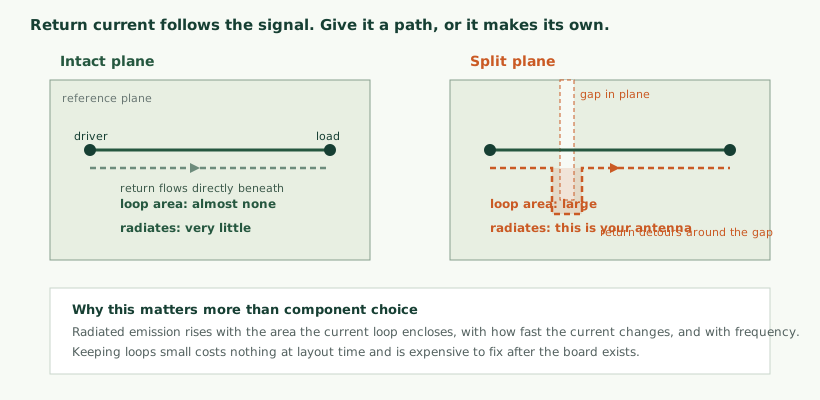
Current that flows out along a trace must return, and at high frequency it returns by the path of lowest impedance, which is directly beneath the signal in the reference plane. That arrangement encloses almost no area and radiates very little.
Put a gap in the plane under that trace and the return current cannot follow the direct path. It detours around the obstruction, and the loop it now encloses can be large. That loop is an antenna, and it was created for free by a decision that looked like a routing convenience.
This single mechanism accounts for a substantial share of radiated emissions failures. Keeping reference planes continuous beneath signals, particularly fast ones, is one of the highest-value habits in EMC-aware layout and costs nothing.
The usual sources, in order of how often they cause trouble
Switching converters
A switching regulator works by turning current on and off quickly, which is precisely the behaviour that radiates. The critical area is the loop carrying the fastest current changes, and minimising its enclosed area is the single most important layout decision in the circuit. The components forming it should be placed tightly together with short, wide connections, before anything else is positioned.
Input filtering matters too, and should be designed rather than populated hopefully. A converter with no deliberate input filter will put its switching noise straight back onto the supply, which is what the conducted emissions test measures.
Switching frequency is also a lever. Some converters can be synchronised or spread over a range, which distributes energy rather than concentrating it at harmonics of a single frequency. That can be the difference between a narrow peak over the limit and a broad hump beneath it.
Cables
Above roughly thirty megahertz, cables are usually the dominant radiating structure. Boards are small relative to the wavelengths involved; cables are not, and a cable a metre long is an efficient antenna across a wide range.
The mechanism is common-mode current: a small noise voltage between the board’s reference and the outside world drives current along all conductors of a cable together, and that current radiates. It is not the intended signal; it is a fraction of a milliamp of noise riding along with it.
Remedies are filtering at the point the cable leaves the board, common-mode chokes, and careful attention to how the connector relates to the reference. The important word is “at the connector”: a filter placed after the signal has already travelled across the board has allowed the noise to couple everywhere on the way.
Clocks and fast edges
Anything switching quickly generates energy at multiples of its frequency, and a signal with very fast edges contains energy far above its fundamental. A clock is the obvious case; a fast logic output driving a short trace is the less obvious one.
The practical measures are keeping such signals short and away from anything leaving the board, and slowing edges where speed is not needed. A small series resistor on a signal that only has to be correct at a modest rate costs almost nothing and removes high-frequency content that would otherwise have to be dealt with later.
The enclosure
A conductive enclosure helps, but its effectiveness is determined by its openings rather than its material. A slot behaves as an antenna when its longest dimension becomes significant relative to the wavelength, so a long thin gap can leak far more than a round hole of similar area. Ventilation is better provided by many small holes than by a few large slots.
How the enclosure is bonded matters as much. A shield connected through a short wire has that wire’s inductance in the path, which undermines the shielding at exactly the frequencies where it is needed. Connections that are short and made around the full circumference are substantially more effective than a single point connection, and this applies to cable shield terminations as much as to enclosures.
Decisions that are cheap now and expensive later
It is worth being concrete about which choices have to be made early, because the cost of revisiting each differs enormously.
| Decision | Best taken at | Cost of changing later |
|---|---|---|
| Layer stack-up and plane arrangement | Before layout | Complete board respin |
| Where the switching converter sits | Before placement | Board respin |
| Space for interface filtering at connectors | Before placement | Respin, or awkward retrofitted components |
| Protection devices at every external interface | Schematic | Respin, though sometimes retrofittable |
| Provision for series resistors on fast signals | Schematic | Cheap if pads exist, respin if not |
| Enclosure material and aperture arrangement | Mechanical concept | New tooling |
| How the board bonds to the enclosure | Mechanical concept | Mechanical change, often significant |
| Cable types and shield termination | System design | Usually modest, sometimes the easiest lever available |
| Clock frequency selection | Schematic | Firmware and possibly hardware |
The pattern is that almost everything effective is a layout or mechanical decision, and almost everything cheap to change late is a cable or a ferrite. That asymmetry is why EMC review before fabrication is worth so much more than EMC support afterwards: at the earlier point every option is still available, and at the later point you are choosing among the few that remain.
A practical hedge for designs where the risk is uncertain: provide unpopulated footprints for filtering and protection at interfaces and on fast signals. They cost almost nothing on a bare board and mean a problem discovered at test can often be resolved by fitting parts rather than by revising the design. Engineers who have been through this once tend to do it thereafter.
Immunity, and why it is a different discipline
Emissions is about containing energy. Immunity is about tolerating it, and the design measures differ.
Electrostatic discharge is the most common immunity failure and the most predictable. Anything a person can touch will eventually receive a discharge, and the energy takes the lowest impedance path to wherever it can reach. Protection devices at the point of entry, with a short low-impedance path to the reference, are the standard measure. Placing protection close to the connector matters enormously; protection at the other end of a trace has allowed the discharge to travel across the board first.
Radiated and conducted immunity failures usually appear as a measurement drifting, an input misreading, or a processor resetting while the field is applied. Sensitive analogue inputs and long cables are the usual routes in, and designing those inputs properly is covered in sensor selection and signal conditioning. Filtering at interfaces helps both emissions and immunity, which is one reason interface filtering is such a good investment.
Surge and fast transients are about survival rather than continued operation. For mains-connected equipment and anything with long external cabling, appropriate protection is necessary, and the coordination between protection stages matters: a fast device that clamps early paired with a device that handles the energy.
A useful design question throughout: what is this product’s defined behaviour when it is disturbed? For some tests, continued correct operation is required; for others, a temporary loss of function with automatic recovery is acceptable. Knowing which applies to your product tells you whether a reset during a burst is a failure or an acceptable outcome, and that materially affects the design effort required.
Grounding, which causes more arguments than anything else
Few topics in electronics generate as much confident contradictory advice. Some of it is outdated, some of it was correct for a different kind of circuit, and some is repeated without anyone remembering why.
The idea that causes most trouble is that grounds should be separated: analogue from digital, quiet from noisy, with a single connecting point. For low-frequency precision circuits this reasoning has merit, because it prevents noisy return currents flowing through a sensitive reference. For anything with fast signals it is frequently harmful, because a split plane is exactly the obstruction described earlier, and a signal crossing the gap forces its return current on a long detour.
The more reliable modern guidance for mixed designs is to keep the reference plane continuous and to control where currents flow by careful placement instead. Put the noisy circuitry in one area and the sensitive circuitry in another, route signals so they do not cross between regions unnecessarily, and let the plane remain whole. Partitioning by placement achieves what splitting the plane was trying to achieve, without creating an antenna.
There are genuine exceptions, particularly where isolation is required for safety or to break a ground loop, and in those cases the separation is deliberate and complete rather than a gap in an otherwise shared plane. The distinction worth holding on to is between isolating two domains properly and cutting a slot in a plane and hoping.
Chassis and signal reference is a related question with a similar pattern. Whether and where the board’s reference connects to the enclosure affects both emissions and immunity, and the answer depends on the product. What is consistently true is that the connection, where it exists, should be short and low impedance. A long wire from board to chassis has inductance, and at the frequencies that matter it is not the connection it appears to be on a schematic.
Decoupling, briefly
Local decoupling capacitors supply the fast current demands of switching devices so that the demand does not have to travel across the board from the supply. Their effectiveness depends less on capacitance value than on the loop area between the capacitor, the device it serves and the reference plane. A capacitor placed near its device with short connections to the plane is doing its job; one placed conveniently at the edge of the device outline with a long connection is largely decorative at high frequency.
This is another decision that costs nothing at layout and cannot be corrected afterwards, and it is worth checking specifically during a pre-fabrication review.
Pre-compliance: useful, and not a substitute
Measuring before the formal test is worth doing, provided everyone is clear about what it does and does not establish.
What it does: finds gross problems while they are cheap to fix, identifies which part of the circuit a particular emission comes from, and gives an approximate indication of margin. Near-field probing to locate a source is particularly valuable and needs relatively modest equipment. Comparing a proposed fix against a baseline is reliable even when the absolute numbers are not.
What it does not: produce results that can be submitted, or prove compliance. Measurements outside a properly characterised environment are affected by the surroundings, and the uncertainty is not quantified. Treating a pre-compliance pass as a guarantee is a way to be surprised at the test house.
The most valuable use is comparative. Establish a baseline, change one thing, measure again. That tells you whether an intervention helped and by roughly how much, which is exactly the information needed during design.
The test day
A few practical matters make the difference between a productive day and a wasted slot.
- Take spares and the means to modify. Additional units, a soldering iron, assorted ferrites and capacitors. A problem identified at ten in the morning can often be resolved by lunchtime if you can act on it.
- Bring the product as it will ship. Same enclosure, same cables, same accessories. A unit tested with different cables has been tested as a different product.
- Know how to exercise it. The product must be operating in its worst-case mode, and you need a way to confirm it is still functioning correctly during immunity tests.
- Attend. A test house can tell you that a frequency failed. Someone who knows the design can often tell you why, and try something.
- Record everything you change. It is easy to leave with a passing result and an incomplete account of which modifications produced it.
- Expect the first attempt to find something. Planning the schedule as though it will pass first time is optimistic.
Working with a test house
The relationship with the laboratory makes a substantial difference to how the process goes, and a little preparation changes what you get from it.
Involve them before you need them. A conversation at design stage about which standards apply, what the test setup will look like and what they will need from you costs nothing and prevents the most common surprises. Test houses generally welcome this, because a well-prepared client makes their day easier too.
Ask what the setup will be. How the product will be positioned, what cables will be attached and how they will be routed, what will be used to exercise it. Cable routing in particular can change results noticeably, and knowing the arrangement in advance lets you test in a comparable configuration.
Be specific about operating modes. The product should be tested in its worst case, and you are better placed than the laboratory to know what that is. A device that transmits periodically, drives a motor intermittently or charges a battery has modes that differ substantially, and testing the quiet one proves little.
Understand what the report will say. A report is evidence that a specific sample, in a specific configuration, met specific limits on a specific day. It is not a statement that your product line is compliant in perpetuity, which is why the record of subsequent changes matters.
Ask about measurement uncertainty. Every measurement has it, and a result within the uncertainty of the limit is not as comfortable as a number under a line suggests. This is another argument for margin.
If it fails
A failure is information rather than a verdict, and how you respond determines the cost. Get the frequencies and the amounts, because both matter: two decibels over at one frequency is a different problem from fifteen decibels over across a wide band. Ask whether the emission moved when cables were repositioned, which points immediately at whether the cable or the board is radiating. And if time in the chamber remains, try the cheap interventions while you are there, since a ferrite that removes the problem tells you a great deal about the mechanism even if it is not the final fix.
Resist the temptation to apply fixes without understanding why they worked. A ferrite that happens to solve a problem, fitted without knowing what it is doing, is a fix that may not survive a component change, a cable substitution or a different production batch. Understanding the mechanism is what makes a fix durable.
Common failures and where to look
| Symptom | Usual cause | Where to look |
|---|---|---|
| Broad elevated emissions above 30 MHz | Common-mode current on cables | Interface filtering, connector grounding, cable routing |
| Narrow peaks at regular intervals | A clock and its harmonics | Which oscillator matches the spacing; routing of that signal |
| Conducted emissions in the lower range | Switching converter | Input filter design, switching loop area |
| Emissions change when a cable is moved | The cable is the radiator | Filtering at the connector, common-mode chokes |
| Resets during fast transient testing | Insufficient supply filtering or decoupling | Power entry filtering, local decoupling, reset circuit |
| Analogue readings drift under a field | Sensitive input picking up interference | Input filtering, shielding, cable type |
| Damage during discharge testing | No protection, or protection too far from entry | Protection devices at connectors and their return path |
| Passes with the lid off, fails with it on | Enclosure resonance or a cable relocated by assembly | Internal cable routing, enclosure bonding |
Firmware can help, and can hurt
EMC is usually treated as a hardware discipline, and mostly it is, but software makes a difference in both directions and it is often the fastest lever available late in a project.
What firmware can improve. Reducing clock frequencies when full speed is not required lowers high-frequency content directly. Configuring output drive strength to the minimum that works slows edges. Disabling unused peripherals and their clocks removes sources entirely. Spreading activity rather than performing it all synchronously avoids concentrating energy at a single repetition rate. Where a switching converter supports it, adjusting its frequency or enabling a spreading mode can move a peak away from a troublesome frequency.
What firmware can make worse. Enabling high drive strength by default, which many initialisation routines do without anyone deciding. Polling a peripheral in a tight loop at a fixed rate, creating a strong periodic signature. Leaving a debug interface or a high-speed peripheral active in production. Servicing a regular interrupt at exactly the wrong repetition rate.
The useful implication is that a marginal failure at the test house can sometimes be addressed with a firmware change rather than a board revision, which is a far better position to be in. It is worth having someone who can rebuild and load firmware present on the test day for exactly this reason.
Immunity behaviour is also a firmware question. When a product is disturbed, what it does is largely a software decision: whether it detects a corrupted transaction and retries, whether a watchdog recovers it cleanly, whether a spurious input is filtered before it is acted upon, and whether it returns to a safe defined state after a reset. Several immunity tests permit temporary loss of function with automatic recovery, and firmware that recovers cleanly turns a failure into a pass.
Radio products
A product containing a radio has additional considerations, and the interaction between them and ordinary EMC work catches people out.
Using a pre-approved module reduces the work substantially compared with designing a radio from components, and for low and medium volumes it is almost always the right choice. What it does not do is remove your obligations: the finished product still has to be assessed, and the module’s approval typically depends on conditions about how it is implemented, including antenna type and layout.
There is also a practical tension. Your own product’s emissions can degrade its radio’s sensitivity, and a switching converter producing noise in the band your radio receives will reduce range without ever showing up as a compliance failure. This is a performance problem that testing may not reveal, and it is worth measuring separately.
Antenna placement interacts with everything discussed here: the enclosure, the ground plane, nearby components and cable routing, and the technology choice itself is covered in choosing IoT connectivity. Deciding it late, after the mechanical design is fixed, is a recurring source of difficulty, as discussed in choosing IoT connectivity.
Beyond EMC: the other requirements in the same envelope
EMC rarely travels alone. A product being prepared for market usually has to satisfy several requirements at once, and they interact in ways that are easier to handle together than sequentially.
- Electrical safety for anything mains-connected or capable of causing harm, which constrains creepage and clearance distances, insulation, and enclosure construction. Those constraints also affect layout, sometimes in tension with the tight loops EMC prefers.
- Radio requirements where the product transmits, which typically cover the radio itself alongside EMC and safety.
- Materials and substances restrictions, which affect component selection and require declarations from suppliers. Gathering that evidence late, across a bill of materials of several hundred lines, is a genuinely unpleasant exercise.
- End-of-life and packaging obligations, which are administrative rather than technical but have deadlines.
- Energy efficiency requirements for some product categories, which can constrain standby consumption.
- Sector-specific requirements for medical, automotive, rail, marine or hazardous environments, which are substantially more demanding and need establishing at the very start because they shape the whole design.
The practical advice is to establish the full list early rather than discovering items sequentially. Each one has lead time, some require evidence from suppliers that takes weeks to gather, and several constrain design decisions that are expensive to revisit. A compliance plan listing every applicable requirement, who is responsible for it and when it must be satisfied is unglamorous project management that repeatedly saves projects from avoidable delay.
Which of these apply to your product depends entirely on what it is and where it is sold, and the requirements change over time. This is a conversation for a compliance advisor or a test house early in the project, not an assumption to carry from a previous product.
Documentation
Testing produces results; the documentation is what demonstrates that the product is what was tested and that its compliance is maintained.
What is typically assembled includes a description of the product, the standards applied and why those, test reports, design documentation such as schematics and layout, an assessment of risks relevant to the applicable requirements, user documentation, and a record of changes made since testing.
The last item is frequently neglected and matters most over time. A product that has quietly accumulated component substitutions and layout revisions since it was tested is not obviously the product that was tested, and the ability to show which changes were assessed and why is what makes that defensible. This connects directly to cost reduction work, where the temptation to substitute components runs into exactly this question.
Planning the compliance work into a project
Compliance is frequently treated as a phase that happens near the end, and treating it that way is what produces the schedule problems it is known for. A more realistic arrangement spreads it across the project.
- At concept. Establish which markets, which product category, and therefore roughly which requirements apply. This determines the limits you are designing against, and designing to the wrong ones in either direction is expensive.
- At architecture. Decide the enclosure approach, how the board bonds to it, what external interfaces exist and what they connect to. These are the decisions with the longest reach.
- Before layout. Agree the stack-up and the placement strategy for the switching converter, the connectors and any radio.
- Before fabrication. Review the layout specifically for EMC. This is the highest-value hour in the whole process, because everything is still changeable and nothing has been paid for.
- On first prototypes. Pre-compliance measurement to find gross problems, with time in the schedule to act on what it finds.
- Book the test slot early. Lead times are longer than most plans assume, and a second slot after a failure may be weeks away.
- After testing. Maintain the record of changes, so that a substitution made eighteen months later can be assessed against what was actually tested.
The single highest-return item on that list is the layout review before fabrication. It costs a few hours and it is the last moment at which the decisions that dominate emissions performance can still be changed for free.
Budgeting realistically
Three costs are routinely underestimated. The first is the possibility of a second test visit, which should be assumed rather than hoped against. The second is the engineering time to investigate and fix whatever the first attempt finds, which is not a fixed quantity and depends on what the cause turns out to be. The third is the board revision that a layout-related failure necessitates, including fabrication, assembly and the lead time attached to both.
A project plan that assumes first-time success with no contingency is not a plan, and the cost of the contingency is much smaller than the cost of a launch date that moves.
A short glossary
| Term | Meaning |
|---|---|
| Emissions | Electromagnetic energy a product produces, measured as conducted onto its cables and radiated into space. |
| Immunity | A product’s ability to operate correctly when subjected to external electromagnetic disturbance. |
| Common-mode current | Current flowing in the same direction along all conductors of a cable. The dominant radiated emissions mechanism above about thirty megahertz. |
| Differential-mode current | The intended signal current, flowing out along one conductor and back along another. |
| Loop area | The area enclosed by a current’s path out and back. Radiated emission rises with it. |
| Reference plane | A continuous conductive layer providing the return path for signals above it. Interrupting it is a common cause of failure. |
| Common-mode choke | A component that impedes common-mode current while passing the intended differential signal. |
| Pre-compliance | Indicative measurement outside an accredited environment, used to find problems early. Not submissible. |
| Margin | The distance between measured emissions and the limit. Headroom for variation and for later changes. |
| Technical documentation | The assembled evidence describing a product, the requirements applied and how they were addressed. |
If you take one thing away
Almost everything that determines whether a product passes is decided before anyone measures anything. Where the return currents flow, how tightly the switching loop is drawn, whether the connector has filtering, how the enclosure is bonded, how fast the edges are.
By the time a unit is in a chamber, those decisions have been made and the available responses are ferrites, cable changes and firmware adjustments. Sometimes that is enough. When it is not, the answer is a board revision and another slot.
The engineering discipline that avoids this is not exotic. It is a layout review before fabrication by someone who knows what to look for, unpopulated footprints where filtering might be needed, and a deliberate decision to design for margin rather than for the limit.
Being clear about what we are
We are an engineering partner, not a test laboratory or a certification body. We do not issue certificates, declarations or approval numbers, and we cannot declare your product compliant.
Compliance is established through testing by appropriately accredited laboratories, against the standards that apply to your product and your markets, and the declaration is made by you as the manufacturer. What we do is design with those requirements in view, investigate problems, prepare the documentation a test house and an assessor will ask for, and support you through the process.
Which standards apply depends on your product, its function, how it is powered and where it is sold, and requirements change over time. Establish this early with a test house or compliance advisor, because it shapes the design rather than decorating it.
Mistakes worth avoiding
- Leaving EMC until there is hardware to test. By then the decisions that matter have been made.
- Splitting reference planes under fast signals. The most common self-inflicted antenna.
- Filtering at the wrong end. Protection and filtering belong at the connector.
- Designing to just pass. No margin means no tolerance for any later change.
- Testing with different cables from the ones shipped. You have tested something else.
- Treating a pre-compliance pass as a guarantee. It is indicative, not conclusive.
- Assuming a module approval covers the product. It covers the module, under conditions.
- Not recording changes made after testing. The compliance argument depends on it.
How we help
- Design review. Schematic and layout assessed against EMC practice, ideally before fabrication, or on an existing design that is failing.
- Design work. Filtering, protection, grounding strategy, layout and enclosure interaction as part of the hardware design. See hardware and PCB design.
- Pre-compliance investigation. Locating sources and evaluating candidate fixes on the bench rather than in an expensive chamber.
- Documentation. Preparing the technical material a test house and an assessor will ask for.
- Test support. Attending where useful, diagnosing failures on the day, and evaluating fixes.
- Change assessment. Determining what retesting a later modification triggers.
The certification process itself — what the mark means, the technical file and working with a test laboratory — is covered in CE, UKCA and FCC certification. The service page for this work is EMC and compliance readiness. For the wider engineering picture, see what industrial IoT actually is.
Questions we are asked about this
What clients ask before starting
Our product failed EMC testing. Can you help?
Yes, and the test report is the most useful thing to send. It identifies which test failed, at which frequencies and by how much, which narrows the investigation considerably before anyone opens the enclosure.
Does pre-compliance testing replace formal testing?
No. Pre-compliance finds obvious problems while they are still cheap to fix and gives an indication of margin. It is not accredited and its results are not a substitute for testing at an appropriate laboratory.
Can you issue our compliance certificate?
No. We are an engineering partner, not a test laboratory or certification body. Compliance is established through testing at appropriately accredited laboratories against the standards applying to your product and markets, and the declaration is made by you as the manufacturer.
How much margin should we design for?
More than you think you need. A product that passes by a fraction of a decibel in one chamber may fail in another, and any later component change can consume the remainder. Several decibels of headroom is a reasonable target and is much cheaper to design in than to recover afterwards.
Will using a pre-approved radio module mean we pass?
It helps considerably and it does not guarantee anything. The module may hold its own approval, but your product as a whole still has to be assessed, and how you lay out the board, route the antenna and handle cables can undo a compliant module.
Does a change to our product mean retesting?
Sometimes. A layout revision, a different switching regulator, a new enclosure material or a cable change can all affect emissions. Which changes require what is a judgement made against the specific product, and it is worth assessing before committing to a change rather than after.
How long does EMC testing take to book?
Longer than most schedules assume, and slots are often weeks out. Booking early and treating the date as fixed is sensible, as is having a plan for what happens if the first attempt fails, because a second slot may not be available quickly.
Which standards apply to our product?
That depends on what it does, how it is powered, whether it contains a radio, and where it is sold. Establishing this early matters because the limits differ substantially and they shape the design. A test house or compliance advisor can confirm it for your specific product.
Where are you in the process?
Tell us whether the design is still open, already fabricated, or has failed a test. If it failed, the test report is the most useful thing you can share.